
GA-92XTd Magnetic Locator

Table of Contents
Introduction
The GA-92XTd magnetic locator detects the magnetic field of ferromagnetic objects. It responds to the difference in the magnetic field between two sensors that are spaced approximately 9.5 inches apart. This difference is referred to as the “signal strength” throughout this manual and is represented in the instrument by an audio tone, the display of a bar graph, and a numeric indication. In addition, the polarity of the signal strength is shown as a + or – sign on the display, and determines the side (right or left) on which the bar graph is displayed. Although most objects can be located using the audio indication alone, simultaneous use of the audio and visual responses will provide additional information to help you pinpoint a target and determine its orientation.
The below graphic illustrates an application of the GA-92XTd locator in which it is used to detect an iron marker used for property line identification. As shown, the magnetic field of the iron marker is stronger at sensor A than it is at sensor B. This creates a signal strength that is larger than zero (which would occur when the field strength is the same at both sensors).
The audio response of the GA-92XTd is designed so that the frequency of the audio tone increases as the detected signal strength increases. As a result, the frequency of the audio output is higher than the idling frequency (~ 30 Hz) that exists when the signal strength is approximately zero. The larger signal strength also causes the bar graph display to peak in either the positive or the negative direction.

Detecting Magnetic Field of an Iron Marker
The GA-92XTd unit can be operated either in the open or closed position and any position in between (see below). The GA-92XTd has an internal detent mechanism to keep the unit in either the fully extended (open) or fully retracted (closed) position. To extend the unit, grasp the looped end of the locator and pull until the shaft locks into place. To return the unit to the closed position, push the looped end back into the shaft. The unit will lock into place.

Open and Closed Positions
NOTE: In the closed position using non-lithium batteries, a slight signal may be detected in the high gain settings even if no ferrous material is present. This can be avoided by 1) decreasing the gain, 2) operating the unit in the extended position or 3) using a lithium battery.
Operating Controls
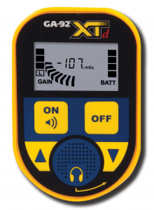
ON / Volume
To turn the unit on, push this button. Upon turn on, the volume defaults to HIGH. Pushing the button a second time changes the volume to MEDIUM. Pushing the button a third time MUTES the volume. Additional pushes of this button cycle the volume through HIGH-MEDIUM-MUTE.
OFF
To turn the unit off, push this button.
GAIN
The sensitivity of the unit can be increased (to detect smaller objects at greater depths) or decreased (to detect larger objects at smaller depths) by adjusting the gain up or down pushing the UP or DOWN arrow buttons.
Visual & Audible Indicators
Gain Level Indicator
The gain range is indicated by a 4-segment LCD as shown in the below graphic: L (Low), M (Medium), H (High) and XH (Extra High). Upon turn on, the gain defaults to M (Medium). Each press of the UP or DOWN arrow buttons will cause the gain level indicator to change accordingly.

Gain Level Indicators
Battery Level Indicator
The battery level is indicated by a 4-segment LCD indicator. When all four segments are black, the voltage level is between 100% and 75%. As the voltage decreases, the number of black segments decreases. Battery life varies with usage and the ambient temperature. Cold temperatures reduce battery life. Low temperatures may result in only two or three segments being black. This could be temporary, and all segments will change to black as the temperature increases.

Battery Voltage Status Indicators
Signal Strength & Polarity Indicator
The signal strength, defined as the difference, or delta Δ, between the magnetic field detected at the top and bottom sensors, is shown as a numerical indication in mG (milligauss) units, is preceded by the polarity of the signal (+ or -), and is followed by the Δ symbol (to emphasize that it represents a “difference” between the two ends of the sensor array).
In addition, the signal strength is shown in a semi-circular bar graph, with more bars indicating a stronger signal. Depending on polarity, the bar graph will switch to the + (right) or – (left) side. The signal strength is also indicated by the frequency of the audio signal; a higher audio frequency indicates a stronger signal.

Signal Strength Visual Indicators
Connectors & Accessories
Headphone Jack
The headphone jack is located on the side of the unit near the face of the locator. Headphones are optional and may be purchased from Schonstedt as an accessory. The headphone jack is monaural. Standard stereo headphones may be used, but they will produce sound in only one ear. When the headphones are plugged in, the speaker sound will be muted, but the ON/Volume button still controls the volume of the headphones.
Headphone Jack Plug
A Headphone Jack Plug has been included with this product. It is recommended that the plug remain inserted into the jack any time that headphones are not in use. This aids in making the instrument more water-resistant.
Battery Replacement

The GA-92XTd is powered by one 9-volt battery. The battery is located in the handle of the instrument and can be accessed by turning the screw counterclockwise. To remove the battery, tilt the unit so that the handle is pointing down, and the battery will slide out. When replacing the battery, look at the outside of the battery door for the proper battery orientation. As a safety measure, the unit will not turn on if the battery is not inserted correctly. You should never have to force the battery door closed. If the battery does not seem to be going in all the way, remove the battery, reverse its orientation and then replace it.
Locating & Detecting Iron Objects

Search Procedure
Turn the instrument ON. The gain defaults to Medium (M). Grasp the locator. Since the upper sensor is located near the handle of the instrument (especially if it is being used in the collapsed position), wristwatches may produce unwanted changes in the audio signal and in the meter indication. Therefore, watches should be removed. Keep the locator away from your shoes as they may contain magnetic material.
To obtain a maximum coverage area, sweep the locator from side to side. When the locator comes within range of an iron object, the signal strength will peak, the frequency of the audio signal will peak, the bar graph will expand in the positive or negative direction, and the digital readout will peak.

NOTE: The number of bars shown in the bar graph, the number displayed in the digital readout, and the frequency of the audio signal will all depend on the signal strength, which is affected by the type of iron object detected, its orientation, and the gain setting.
Basic Signal Patterns
When the GA-92XTd is positioned directly over a vertical target, the signal strength will peak (audio signal, digital readout, and bar graph) at either a positive or negative polarity.
The audio signal, digital readout, and bar graph indications also peak over each end of a horizontal target. One end is positive, the other is negative. This will help you to distinguish between two vertical pipes or one horizontal pipe. Usually two vertical pipes buried in close proximity will produce bar graph indications with the same polarity.

Signals from vertical and horizontal targets
After you have detected the presence of a target, hold the locator vertically and slowly move it back and forth in an “X” pattern while listening to the audio response and observing the bar graph indicator. For a given gain setting, the number of bars will be greatest when the locator is directly over a vertical target or the ends of a horizontal target. The “X” pattern is ideal for pinpointing small objects. A 1-1/4 inch PK nail buried up to 10 inches can be located precisely using this technique.

“X” Pattern Provides Precision Locating
If you are looking for a corner marker and detect two or three signals in the same general vicinity, raise the locator several inches above the ground or decrease the gain setting. Any signal that disappears when the locator is held higher or when the gain is decreased is likely coming from a smaller target. The signal from a rusty bolt or other small item is much weaker than the signal from a larger target, such as an 18-inch length of 3/4 inch rebar which can be located at depths up to 8 feet.

Decreasing the gain eliminates unwanted signals
Strongly Magnetized Markers
A strongly magnetized marker that is at or near the surface will provide a weaker indication on both sides of the marker, and that could be mistaken for the marker.
The heavy line in the below graphic represents the increase and decrease in the audio and bar graph indications as you move the locator over a marker. Between points A and B, the signals increase slightly and then decrease. Just beyond B, the signals increase rapidly, peak directly over the marker and then decrease at point C. From C to D, the signals increase and decrease again. Therefore, if you do not move the locator completely across the marker, you might assume that the weaker indication on either side of the marker is its location. The two weaker indications occur because the locator is extremely sensitive to the magnetic field components that are parallel to its long axis. At points B and C, the field is perpendicular to the locator; therefore, no significant audio or bar graph indications are produced at these points.

Signal Pattern from a Strongly Magnetized Marker
Correct Stake Orientation
When placing stakes, correct orientation is important. For checking purposes, the orientation of the pin relative to the locator is shown in the below graphic. Check the pin with one orientation. Then rotate the pin 180°. The orientation that gives the largest reading is the one that should be used. This reading should be positive in the Northern Hemisphere and negative in the Southern Hemisphere.
An iron pin has two types of magnetization. One is the magnetization induced by the Earth’s magnetic field. The induced magnetization is always downward in the Northern Magnetic Hemisphere and produces a positive output no matter which end of the stake is driven into the ground. The other type of field is the permanent magnetization that is fixed to the pin. For maximum detection, the stake should be driven into the ground such that the permanent magnetization is in the same direction as the induced magnetization.

Checking a Stake’s Orientation
Locating Manholes, Septic Tanks, & Well Casings
The magnetic field is strongest at the edge of a shallow manhole cover. You can easily trace the edges of covers near the surface. Locating depths for manhole covers range up to 9 feet.

Locating Manhole Covers
The great length of a well casing provides a strong field at the surface that makes it easy to locate casings buried up to 16 feet deep.

Locating Water Well Casings
The GA-92XTd can also be used to precisely locate the metal handles or reinforcing bars on septic tank covers at depths of up to 4 feet.

Signal Patterns provided by Septic Tank Covers
Locating & Tracing Barbed Wire
Searching in the vicinity of a chain link fence requires a reduced sensitivity setting and some control over the orientation of the locator. Position the locator horizontally with its long axis perpendicular to the fence. This insures that the upper sensor is kept away from the fence.

Searching in the vicinity of a chain link fence
Perform the search by slowly moving the locator forward along the fence while also moving it to the right and to the left. As you move forward, this technique allows you to search an area several feet wide. Listen for an abrupt drop in the signal that will occur when the lower sensor, located 1-1/2 inches from the end of the locator, is directly over the stake. Any variation in the position of the locator will produce an abrupt rise in the frequency of the signal.

Abrupt drop of signal while searching along a chain link fence
Locating Valve Boxes
Both the valve and its casing, when iron, provide strong magnetic fields that make them easy to locate. Plastic enclosures containing magnets (which are typically used with non-ferrous valve boxes) are easily located at depths of up to 9 feet.

Locating valve boxes & casings
Locating Cast-Iron Pipes
Cast-iron pipes produce the strongest magnetic signals at their joints. After an initial sweep search identifies the general direction of the pipe, the steel pipe joints or transition points can be more accurately traced by the following procedure:
- Set the Sensitivity control to maximum (XH indication).
- Hold the locator vertically approximately 1 to 1-1/2 feet above the surface.
- Walk without turning or tilting the locator.
- Mark the locations where the maximum signal levels occur.
- Return to an area of maximum signal strength and hold the locator several inches
above the surface. The sensitivity will probably have to be reduced during this second pass. Four-inch pipes can be located at depths up to 9 feet.

Signal Patterns Provided by Cast-Iron Pipes
Locating Steel Drums
The GA-92XTd’s signal pattern will vary depending on the vertical or horizontal orientation of the drum and how deep it is buried. A fifty-five gallon drum can be located at depths ranging from 4 feet to 9 feet.

Signal Patterns provided by Steel Drums
Locating Ordnance & Weapons
The versatile, lightweight, cost-effective GA-92XTd is also designed to aid EOD technicians and law enforcement officers during area search operations.

- A 175mm Projectile can be located up to 3 feet deep.
- An 81mm Mortar can be located up to 10 inches deep.
- MK81 Low Drag Bombs can be located up to 7 feet deep.
- A discarded hand gun can be located up to 10 inches deep.
Other Notes
- A burbling sound indicates the presence of an energized power line. This will not influence the meter indication unless it is associated with a magnetic structure.
- The instrument will not respond to non-ferrous metals, such as gold, silver, copper, brass and aluminum.
Specifications
| Battery Indicator | 4-segment LCD |
| Gain | 4-Level LCD - Low (L), Medium (M), High (H), Extra High (XH) |
| Volume | 3 Levels: Muted, Medium and Maximum |
| Input Power | One 9V Battery |
| Battery Life | 24 Hours (intermittent use) |
| Operating Temp | -13° F to 140° F (-25° C to 60° C) |
| Overall Length | Open – 26” (66 cm) Closed – 15.5” (39 cm) |
| Nominal Sensor Spacing | 9.5” (24 cm) |
| Weight | Approximately 2.4 lb (1.1 kg) |
| Water and Dust Resistance | Rated IP54 |
 | This device complies with part 15 of the FCC Rules. Operation is subject to the following two conditions: (1) this device may not cause harmful interference, and (2) this device must accept any interference received, including interference that may cause undesired operation. |
 | Application of Council Directive(s): 2004/108/EC Standard(s) to which Conformity is Declared: EN 61000-6-1:2001, EN61000-4-2, EN61000-4-3, EN 61000-6-3:2004, EN55022:1998 with Amendment A1:2000 (CISPR-22) |
Service & Repairs
If your locator needs service, please return it to the Schonstedt factory (in its case) and complete a Repair Form with the following information:
- Name
- Address
- Telephone and Fax Numbers
- Email Address
- Where Purchased
- Date of Purchase
- Description of Problem(s)
- If unit is out of warranty, an estimate will be provided prior to service work being done.
For Service or Repairs, Ship locator to:
Schonstedt Instrument Company
100 Edmond Road
Kearneysville, WV 25430
Warranty
Schonstedt Instrument Company (Schonstedt) warrants each product of its manufacture to be free from defects in material and workmanship subject to the following terms and conditions. The warranty is effective for 7 years* after the shipment by Schonstedt to the original purchaser. Please complete the warranty registration card and send back to Schonstedt Instrument Company.
Schonstedt’s obligation under the warranty is limited to servicing or adjusting any product returned to the factory for this purpose and to replacing any defective part thereof. Such product must be returned by the original purchaser, transportation charges prepaid, with a description of the defect in writing. If the fault has been caused by misuse or abnormal conditions of operation, repairs will be billed. Specifically, this warranty does not cover product that has been subject to inundation by fire, water or other liquid intrusion, or units that have been damaged or compromised due to repair, alteration or modification by anyone other than an authorized repair representative. Prior to a repair being performed by Schonstedt, a cost estimate will be submitted and no work will be completed until authorized by the customer. Batteries are specifically excluded under the warranty and should be addressed to the manufacturer of batteries in question.
Schonstedt shall not be liable for any injury to persons or property or for any other special or consequential damages sustained or expenses incurred by reason of the use of any Schonstedt product.
* For Military & EOD applications, the warranty is 1 year.
Parts & Accessories
Parts and accessories are available on shop.schonstedt.com. Use the links below to visit the listing in our store. If you need help, please contact Customer Care.
Related FAQs
How do I search along a chain link fence?
Searching in the vicinity of a chain link fence requires a reduced sensitivity setting and some control over the orientation of the locator. Position the locator horizontally with its long axis perpendicular to the fence. This ensures that the upper sensor is kept away from the fence.
 Searching in the vicinity of a chain link fence
Perform the search by slowly moving the locator forward along the fence while also moving it to the right and to the left. As you move forward, this technique will allow you to search an area several feet wide. Listen for an abrupt drop in the signal that will occur when the lower sensor, located 1-5/8 inches from the end of the locator, is directly over the stake. Any variation in the position of the locator will produce an abrupt rise in the frequency of the signal.
 Placement of Locator While Searching Along a Chain Link Fence
How do magnetic locators work?

What are the differences among the GA-52Cx, GA-92XT and GA-72Cd?
The GA-52Cx is an easy to use, reliable, magnetic locator. The GA-72Cd is basically the same as the GA-52Cx but has an LCD meter display reflecting the relative signal strength and polarity of the magnetic field detected. The GA-92XT is a portable, retractable version of the GA-72Cd, providing one-handed operation and easily removable battery.
What is the difference between metal detectors and magnetic locators?
Magnetic locators find objects with ferrous or iron content. They do not react to other metals such as copper, brass, or aluminum, as metal detectors do. Therefore they are less subject to interference from surface debris. Magnetic locators work deeper, measuring a magnetic field originating from the buried target, whereas a metal detector can only detect shallow objects, typically 9 to 12″ inches maximum.

Schonstedt’s magnetic locator, Maggie, searches for subsurface objects.
What type of batteries does my magnetic locator use?
The GA-52Cx and GA-72Cd each operate on two 9-V batteries.
The GA-92 and Maggie each operate on one 9-V battery.
What’s the difference between Magnetic and Pipe & Cable locators?
Many Schonstedt locators look the same, but there’s a BIG difference in how they work and what they find underground. Visit our Whats the Big Difference? Pipe & Cable vs Magnetic page to learn more.
Will your magnetic locators find old coins, brass, gold and such?
No, our magnetic locators will only locate ferromagnetic metals (i.e. iron, steel). Coins, gold and brass do not contain ferromagnetic materials.
Disclaimer
Important notice
Schonstedt believes the statements contained herein to be accurate and reliable; however, their accuracy, reliability, or completeness is not guaranteed. Schonstedt's only obligation shall be to repair or replace any instrument proven to be defective within one year of purchase. Schonstedt shall not be responsible for any injury to persons or property, direct or consequential, arising from the use of any instrument.