
XT-512 Sonde & Camera Locator

Table of Contents
Introduction & Operating Modes

Introduction
The XT-512 Sonde & Camera Locator locates buried pipes and conduits, using mini-transmitting devices, known as sondes. A sonde is a small, battery-operated transmitter that emits a signal used to locate the device. Sondes may also be referred to as “moles” or “beacons” within the industry. For this simplicity throughout this manual, we will refer to them as “sondes”.
To use a sonde, attach it to a pull rope, or a push rod, and manually move the device through the pipe, or conduit, that needs to be located. When a 512 Hz sonde is turned on, it emits a 512 Hz signal that the XT-512 uses to indicate the location and depth of the sonde. In addition to sondes, other devices emit 512Hz signals that may also be located, such as sewer cameras and duct rodders. These devices are the most effective tools for locating non-metallic pipes and conduits buried underground.
Schonstedt has incorporated more than 60 years of experience producing products for aerospace, military, and infrastructure applications into the design of our locators. All Schonstedt products are manufactured following high standards of reliability, durability and performance.
For additional information on pipe and cable locating theory and techniques, check the training section of our website at www.schonstedt.com/training.
 Sonde Mode
When the XT-512 is turned on, it will default to sonde mode. Sonde mode is used to trace non-metallic pipes, or metallic pipes where other modes are inapplicable or inefficient. A small beacon transmitter, or sonde, is pushed through the pipe, and the receiver searches for the signal emitted by the sonde.
Since the signal being traced by the receiver is produced by the sonde and not travelling along the pipes, there are some differences in the way the receiver is used. Due to the nature and strength of the sonde signal, it is necessary to have some idea of where the sonde is (in order to narrow the search area to a radius of several feet centered on the sonde).
Passive Mode: 50/60 Hz
In passive mode, the sonde is not used. Instead, the receiver searches for an appropriate harmonic of 60 or 50 Hz signals (factory preset). These signals are typically present in energized power cables, making it possible to locate them without using a transmitter to impose a tracing signal onto them.
Operating Recommendations
When using the XT-512, follow these tips and recommendations to improve and facilitate your locating experience:
- When operating in passive mode, be aware of your surroundings and possible interference from overhead power lines, other buried utilities carrying 50 or 60 Hz signals, nearby transformers, and/or nearby substations.
- In all operating modes, always set the gain at the minimum setting that shows a clear peak over the Optimum results will most likely be obtained with a signal strength reading between 200 and 800. A consistent reading of 995 or higher indicates the signal is too strong and the receiver gain and/or transmitter power should be reduced.
Controls & Indicators
Automatic and Manual Gain
The XT-512 has the ability to operate in an automatic or manual gain mode. In automatic gain mode, the sensitivity of the receiver is adjusted automatically, based on the strength of the detected signal, to produce a relatively constant and strong signal strength indication. In manual gain mode, the user can adjust the sensitivity up or down to suit different locating scenarios.
Directional Indication
The XT-512 is equipped with directional indicators (arrows). These visual and audible indicators help the user locate the pipe or cable by showing which direction he/she should move in order to get closer to the target when locating in passive mode. These indicators are not available in sonde mode.
Depth Measurement
The XT-512 has the ability to measure the approximate depth of the target pipe or cable being traced. When a depth measurement is made, the receiver must be fully extended and the bottom tip of the receiver must be touching the ground. Depth measurements should only be made when the directional indication says that the target is close and the receiver’s signal strength is maximized (peaked) over the target. Special considerations are required for Sonde mode.
Searching for a Sonde
Once in the surroundings of a sonde, it is important to differentiate whether you are positioned along the axis of the sonde (the direction of the pipe) or off to either side. In the sonde mode, the directional indication is not functional; the signal strength is the only indication available.
Rotate the receiver back and forth and move in the direction that produces the maximum (peak) signal strength. As the receiver gets closer to the sonde, the signal strength increases and it will hit a peak when the receiver is directly over the sonde. Slowly rotate the receiver to fine tune the peak signal strength, which will occur when the plane of the sensors is parallel to the axis of the sonde. For verification, rotate the receiver 90 degrees and see that it produces a “null” (signal strength very close to zero), and then counter-rotate 90 degrees to go back to the original position.
To measure depth, simply place the tip of the unit on the ground and press the DEPTH button when the signal strength is at a peak. The achievable depth depends on a number of factors, but typically it is possible to read depth up to 5 to 15 feet (1.5 to 4.2 m).
Controls
The XT-512 controls are designed to be intuitive and require a minimum of training for effective use. The receiver can easily be operated with one hand.
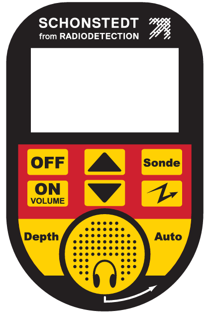
- ON/VOLUME – This switch powers on the receiver and automatically sets the volume to Additional depressions of this switch will cycle the volume through Mute, Medium, and High settings.
- OFF – This switch removes power from the receiver.
- UP/DOWN ARROWS – When the receiver is operating in manual gain mode, pressing the UP or DOWN arrows will increase or decrease the gain from its current When the receiver is operating in the automatic gain mode, the first press of the UP or DOWN arrow will switch the receiver to the manual gain mode.
- AUTO – When the receiver is operating in the manual gain mode, pressing the AUTO button will switch the receiver to operate in the Automatic gain In this mode the receiver adjusts its sensitivity as a function of the strength of the detected signal.
- DEPTH – When the proper conditions to measure depth are present, pressing this switch will display the target’s depth on the LCD (after a delay of 2 seconds). The depth will continue to be displayed on the LCD, along with the “depth symbol”, for as long as the switch is If the switch is pressed and quickly released, the depth will show on the LCD momentarily. The Rex is factory set to display depth in feet and inches or in meters. If the depth cannot be determined due to a weak signal or interference signal by other nearby utilities (congested underground) the LCD will show 3 dashes “—“.
- SONDE – Pressing this switch will cause the receiver to go to the sonde mode of If the receiver is already operating in sonde mode, pressing this switch will have no effect.
- PASSIVE – Pressing this switch will cause the receiver to go to the passive mode of The receiver will momentarily display “50” or “60” to indicate the line frequency being located in this mode. If the receiver is already operating in passive mode, pressing this switch will have no effect.
Visual & Audible Indicators
The information display areas for the receiver are easy to understand. In addition, the receiver has audible indicators to facilitate operation in heavy traffic or noisy areas. All visual indicators for the receiver are on the LCD display, which has six general areas to display information to the user: a Battery Indicator, a Gain Indicator, a Frequency/Mode Indicator, a Direction Indicator, an Alphanumeric Display and a Volume Indicator.
- BATTERY INDICATOR

- The battery symbol indicates the receiver’s battery When all 3 segments inside the battery symbol are present, the battery is fully charged. When only the 2 bottom segments are present, the battery has a medium charge. When only the bottom segment is present, the battery has a low charge and should be replaced. If there are no segments present, the battery is extremely low and you should replace it immediately.
- GAIN INDICATOR

- The “Ⓐ” indicates that the gain is in the automatic In this mode, the receiver adjusts its sensitivity as a function of the strength of the detected signal. No bar graph is shown in this mode.
- If the “Ⓐ” is not visible, the receiver is operating in the manual gain mode; therefore, a means to show the user the relative gain setting is necessary. The bar graph indicates the relative strength of the gain.
- Each time the UP or the DOWN arrow is pressed, the gain is adjusted by 1/30th of the full scale range and the gain level, preceded with an “L”, is shown temporarily to the user on the main signal display.
- The bar graph will change with approximately 6 presses of the UP or DOWN arrow.
- The user may press and hold the UP and DOWN button to change the gain rapidly.
- FREQUENCY/MODE INDICATOR – The upper left of the LCD shows the currently selected mode. In sonde mode, the “512Hz” icon and “Sonde” icon are displayed. In Passive mode, the “Passive Arrow” is displayed.
- (*) The default sonde frequency is 512Hz. XT-512 has the capability to locate a number of alternate legacy Schonstedt sonde frequencies. For more information on these and how they are displayed, contact the factory.
- (**) The number 50 or 60 shows briefly on the numeric display upon entering this mode, indicating which line frequency the unit is programmed to locate in passive mode.
- Direction Indicator / Guidance Arrows – The arrows and center bar in this indicator tell the operator in which direction to move the receiver in order to be directly over the The direction indicator does NOT work in the Sonde operating mode; it is only displayed in passive mode.

- Right Arrow: Receiver should be moved to the right to get closer to the target.
- Left Arrow: Receiver should be moved to the left to get closer to the
- Both Arrows and Center Bar: Receiver is placed close to or directly over the target. This is also accompanied by a beeping sound.
- When all three elements of this indicator are OFF, the signal strength is not adequate to make a directional determination or you are not close to the pipe or cable being traced. Keep searching based on the signal strength indication and the audio feedback, until one of the arrows comes ON.
- ALPHANUMERIC DISPLAY – The alphanumeric display is used to display signal strength and The numeric display is also used for temporary indications of certain operating modes, frequencies, and other brief information messages, as noted throughout this manual.
- Signal Strength – This is an indication of the relative signal level detected by the receiver and is a function of the gain Good signal strength will typically be between 200 and 800.
- The display range for signal strength is 0 to 999; however, very high signal strength is not necessarily better.
- If readings of 995 or higher are consistent, the signal is too strong and steps should be taken to reduce it.
- If a reading of “OL” is observed, a signal is present which interferes with the signal the receiver is set to detect. Steps should be taken to identify the source of interference or to change the locating mode.
- Depth Reading

- When measuring depth, the “depth” icon lights up in the lower right of the display, and the depth of the target is displayed (in feet and inches, or meters – depending on the factory setting). The display range for depth in feet and inches is 0″ to 19’ 9″ and in meters is00 m to 5.99 m.
- VOLUME INDICATOR

- The volume indicator consists of a speaker symbol with 3 sound wave.
- If the volume is off, the speaker symbol with NO bars is shown, for medium volume the speaker symbol with 2 bars is shown, and for maximum volume the speaker symbol with 3 bars is shown.


Connectors & Accessories
The receiver has a standard 3.5mm headphone jack that accepts any mono or stereo earphones or headphones. Schonstedt also supplies headphones as an optional accessory. The receiver automatically detects the insertion of the headphones or earphones and routes the audio signals to them, silencing the internal speaker.
The receiver comes fitted with a rubber plug to protect it from water and dust ingress. It is recommended to keep the rubber plug inserted in the earphone jack when earphones are not being used. The receiver also comes standard with a belt holster for hands-free carrying.
The receiver is shipped factory ready to detect sondes or other devices, such as inspection cameras, that transmit at 512 Hz; however, the sondes themselves are optional accessories also available through Schonstedt.
Battery Replacement
The XT-512 receiver is powered by one 9-volt alkaline disposable battery. The battery is located in the handle of the instrument and can be accessed by turning the screw counterclockwise. To remove the battery, simply tilt the unit so that the handle is pointing down, and the battery will slide out. When replacing the battery, look at the outside of the battery door for the proper battery orientation. As a safety measure the unit will not turn on if the battery is not inserted correctly. You should never have to force the battery door closed. If the battery does not seem to be going in all the way, remove the battery, reverse its orientation and then replace it.
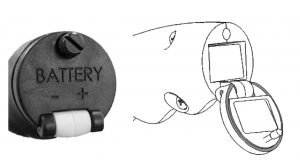
Battery Door and Compartment
Specifications
Specifications
- Operating Frequency:
- Passive: 50 or 60 Hz
- Sonde: 512 Hz
- Battery: One 9V Alkaline Battery
- Battery Life: 12 hours (intermittent use)
- Audio Output:
- 10 – 1500 Hz (determined by signal strength)
- 0 – 70 db SPL (volume controlled)
- Weight (incl. battery): 2.8 lbs. (1.25 kg)
- Operating Temperature: -4°F to 140°F (-20°C to 70°C)
- Water and Dust Resistance: Rated IP54
- Overall Dimensions:
- Closed: 17.5” x 3” x 8.5” (44 cm x 7.6 cm x 21.5 cm)
- Extended: 27.7” x 3” x 8.5” (70 cm x 7.6 cm x 21.5 cm)
- Max. Depth Capability: Approximately 19′ (5.8 m)
- Sonde Mode: approximately 5′- 15′ (1.5 m – 4.2 m)
Regulatory Compliance and Declaration of Conformity
FCC:
++++
This device complies with Part 15 of the FCC Rules. Operation is subject to the following two conditions: (1) this device may not cause harmful interference, and (2) this device must accept any interference received, including interference that may cause undesired operation.
++++
Industry Canada:
++++++++++++++
CAN ICES-3 (B)/NMB-3(B)
CE Mark:
++++++++
Application of Council Directive(s): Directive 1999/5/EC (R&TTE Directive)
Standard(s) to which Conformity is declared:
ETSI EN 301 489-1 V1.9.2 (2011-09)
ETSI EN 301 489-3 V1.6.1 (2013-08)
ETS1 EN 300 330-2 V1.6.1 (2015-03)
Directive 2011/65/EU (RoHS2)
Standard to which conformity is declared: EN 50581:2012
This device should only be cleaned using a dry cloth. Do not use any solvents that could damage the labels.
Technical Support & Service
Radiodetection, LLC offers technical support and sales support on Schonstedt products. For any reason, regarding usage and application, please contact our technical support team at 1-888-367-7014.
- For Service & Repairs, complete a Repair Form and ship unit to Schonstedt, Attention Repairs, 100 Edmond Road, Kearneysville, WV 25434 USA.
- Return instructions and return form are located online at: https://www.schonstedt.com/support/repair-department/
Warranty
Radiodetection, LLC warrants Schonstedt products of its manufacture to be free from defects in material and workmanship subject to the following terms and conditions. The warranty is effective for 3 years after the shipment by Schonstedt to the original purchaser. Please complete the warranty registration card online at www.schonstedt.com/welcome.
Radiodetection, LLC’s obligation under the warranty is limited to servicing or adjusting any product returned to the factory for this purpose and to replacing any defective part thereof. Such product must be returned by the original purchaser, transportation charges prepaid, with a description of the defect in writing. If the fault has been caused by misuse or abnormal conditions of operation, repairs will be billed. Specifically, this warranty does not cover product that has been subject to inundation by fire, water or other liquid intrusion, or units that have been damaged or compromised due to repair, alteration or modification by anyone other than an authorized repair representative. Prior to a repair being performed by Schonstedt, a cost estimate will be submitted and no work will be completed until authorized by the customer. Batteries are specifically excluded under the warranty and should be addressed to the manufacturer of batteries in question.
Radiodetection, LLC shall not be liable for any injury to persons or property or for any other special or consequential damages sustained or expenses incurred by reason of the use of any Schonstedt product.
Parts & Accessories
Parts and accessories are available on shop.schonstedt.com. Use the links below to visit the listing in our store. If you need help, please contact Customer Care.
Disclaimer
Important notice
Schonstedt believes the statements contained herein to be accurate and reliable; however, their accuracy, reliability, or completeness is not guaranteed. Schonstedt's only obligation shall be to repair or replace any instrument proven to be defective within one year of purchase. Schonstedt shall not be responsible for any injury to persons or property, direct or consequential, arising from the use of any instrument.